
Nodes
Ladies and gentlemen, welcome to this extracurricular course on the anatomy of a node. We’ll be dissecting several nodes throughout this course, there may be blood, be warned… In this article we will go through how nodes work, how to use inlets and outlets, learn about flow and discuss the fine art of instantiation.
Nodes
We’ll distinguish nodes into four different categories.
Input nodes, Output nodes, UI nodes and General nodes.
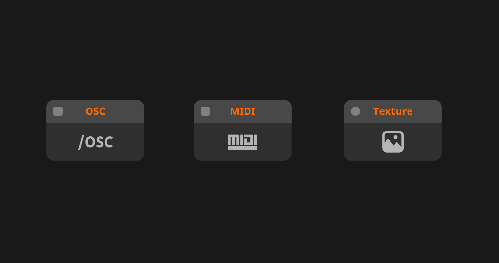
Input Nodes
Input nodes take data from outside into Wire.
This can be information from the host like FFT, Parametric data or slices.
The simplest example is the Texture Input node.
This takes the input from the host and feed it through your patch.
This is the cornerstone of making effects.
A less obvious example is the Trigger Input node.
This requires the user to click the trigger button to have it send out a trigger.
Taking information from outside(the user clicking the button) into Wire (the trigger signal).

Output Nodes
Output nodes output information from your patch to something outside of Wire.
For example: the Texture Output node takes you image and send it to the host.
General Nodes
This is the meat and bones of Wire. This is where the magic happens. These nodes deal with data, textures, arrays and shapes. They modulate, displace and subtract each other. They mix, match, compare and do all the hard math for you.

Comments
The comment node has no inlets or outlets and is instead used to add written comments to your patch, explaining to yourself or others how things work.
Comments can be made hollow by disabling the "fill" toggle in the node panel.
Nodes can be placed within this hollow space, which allows you to divide your patch into sections.
Besides the fill toggle you'll find options for text size and text alignment in the node panel.

Inlets and outlets
Each node has one or more inlets and/or outlets.
These are the dots next to the name of the node.
Inlets are always on the left side and outlets always on the right side.
When you hover over an inlet or outlet a small list will appear containing all the possible data types that can go into this.
When data is flowing through the inlet or outlet, the value will be previewed above the list.
You can always manually adjust values by clicking the value and typing in a new one, dragging the value up and down or adjusting it in the node panel.
You can connect an outlet to an inlet or an inlet to an outlet by clicking on them.
If you connected a something to the wrong inlet you can always reconnect that inlet to the correct inlet, also by clicking it.
Additionally you can drag and drop a cord onto an existing cord to replace the connection.
This works with all types of flow.
Event flow has an additional trick up its sleeve.
Holding down the ALT-key while doing the replacement action the cord will be added to the existing cord.

Modifying nodes
There are a few ways you can modify and change a node.
Expose Inputs
You can right click on a node and select Expose Inputs to create interactive elements. For each numerical input there will be a value box, each toggle gets a boolean and each trigger gets a trigger node connected to it. It makes your patch a little messy, but it might help you to work faster.

Visibility
Not all features of each node are visible. Some nodes have features that have only a few use cases so we’ve hidden them for convenience. You can adjust the visibility of a node by right clicking it and navigating to Visibility. Here you can turn on and of the inlets and outlets that you desire.
There is also the option to hide all [CTRL, SHIFT, H] or show all [CTRL, SHIFT, ALT, H]. This can be useful to make your patch more readable as well as satisfy your OCD because all the blocks can now be the same size!
Thumbnails
Thumbnails can be useful to show what is happening in your patch.
You can enable or update thumbnails by right clicking on the node(s) and selecting the desired option from the menu.
You can use the shortcuts [CTRL + T] to turn thumbnails on/off. The shortcut [CTRL + SHIFT + T] is used to update a thumbnail.
Flow
Data can flow in three ways: event, signal and attribute.
The flow of a node determines when data is transmitted.
You will find that some nodes will only work in a given type, whilst others are flexible and can operate at multiple or all flow types.
But don’t worry about flow too much, Wire will often choose the correct variant for you.
It is more important to understand the difference between the three when working with Wire.

Signal
Signal flow is transmitted at frame rate.
This is the most "up to date" flow type and also the most common in Wire.
The type is denoted by circular inlets and outlets
Event
Event flow is transmitted when the user triggers the node or when the value is changed.
This is most frequently used in randomisation, sending/receiving midi data and triggering nodes.
Events are independent from the frame rate and multiple triggers can occur on the same frame.
the type is denoted by rectangular inlets and outlets
Attribute
Attribute flow is only transmitted while the patch compiles.
This means that changing parameters in attribute flow will force the patch to recompile.
Attribute flow is most frequently used to set resolutions, change node modes, adjust the size of a collection or create constants.
Attribute flow parameters cannot be animated in the host.
This type is denoted by diamond-shaped inlets and outlets.
Conversion
Event and Attribute flow can always be connected to signal inputs.
The OnChange node can be used to convert signal flow to event flow.